Relays are remotely controllable electric switches. Most relays you know are power relays, like the clickers and clackers in your thermostat and your car. But what are signal relays? And no, we do not here mean the automotive turning signal relays.
In this article, I am going to explain what signal relays are when and how to use them. Shortly put, signal relays are small mechanical relays with modest voltage and current ratings intended for switching low-power control and measurement signals. They are similar to power relays, but smaller, faster and rated for lower currents and voltages.
We are next going to explore signal relays in detail: what are they, what are they for, and how they relate to other types of relays. If you are interested learning more, read on!
What are signal relays?
Similar to power relays, signal relays are electrically operated mechanical switches, which open or close a primary circuit (load) based on a control voltage in a separate secondary circuit (coil). Like power relays, signal relays have moving contacts that effect the switching, and these contacts are moved between the open and closed positions by a magnetic force. This magnetic force is created by the control current running in a coil close to the contacts.
What are signal relays used for?
Whereas power relays switch high currents or voltages, signal relays are used to switch small measurement and control signals between different parts of circuits. Although the limit is not exact, signal relays are usually specified for switching load currents lower than 2 A.
Signal relays are sometimes called low signal relays to emphasize that the signals are low current and voltage.
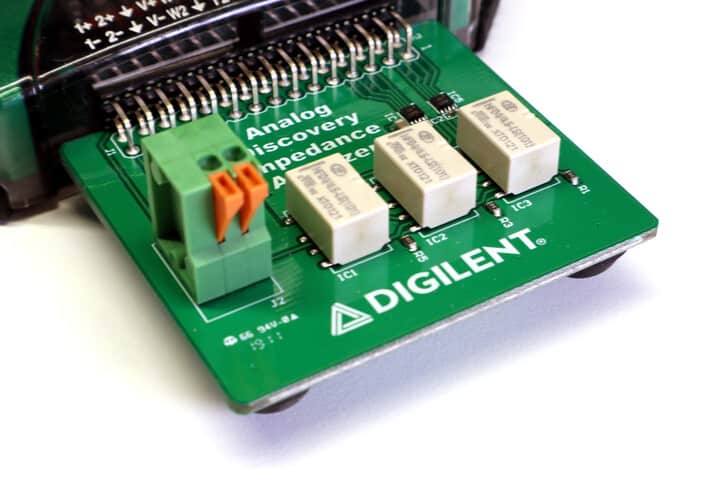
Common use cases for signal relays include switching resistors and capacitors in adjustable signal filters, relay-based multiplexers and RF switches.
Signal relays vs. Power relays
Signal relays and power relays are very similar in construction, and differ mainly in size and voltage and current ratings:
Power relays are rated for 250 VAC or 30 VDC and currents upwards from 2 A. Their size varies from small PCB mount slim packages to large panel mount screw terminal modules.
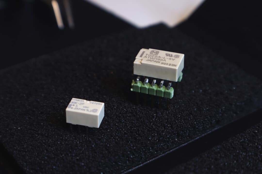
Signal relays have voltage ratings between 5 VDC and 30 VDC; AC specs are sometimes given, but only to 125 VAC. Current ratings are 2 A or less. Signal relays come in relatively small PCB mount brick packages, either through-hole of SMD, although some versions are available in panel or DIN rail packages.
Other minor differences include:
- Switching time: Signal relays may also offer slightly faster switching (~3 ms) than power relays (5…10 ms typ.) thanks to their smaller size.
- Switch form: The most common contact form of signal relays is DPDT by contrast to SPST of power relays
- Insertion loss: Signal relays may be used for switching radio-frequency (RF) signals, and have a spec for insertion loss
Signal relay specifications
The most important signal relay specifications you should check when selecting the model are:
- Contact form: the switch configuration – how many poles, throw, normally open (NO) or normally closed (NC). SPST, SPDT and DPDT are common, but higher pole counts are available (4PDT, 6PDT).
- Voltage rating: the maximum voltage to be switched. Often expressed as current–voltage pair, such as 1A@30 VDC. Typical ratings are between 5 VDC and 30 VDC; sometimes AC specs are given to 125 VAC
- Contact current: the maximum current to be switched. Often expressed as current–voltage pair, such as 1A@30 VDC. Current ratings at DC are typically between 500 mA and 2 A.
- Contact resistance: resistance the relay adds to the load circuit. Ratings typically specified as maximum values, e.g. “100 mOhm max.”
- Coil voltage: the control voltage for which the relay coil is rated. Typical ratings are 3 VDC, 4.5 VDC, 5 VDC and 12 VDC, but higher ratings up to 48 VDC are also available. Usually selected by the logic level of the circuit.
- Coil current: the DC current that the coil takes with the rated coil voltage. Common coil currents are between 5 and 100 mA; relays rated for low coil voltages usually take more current to switch.
Other specs include coil resistance and power (can be deduced from voltage and current), switching times, durability, insulation resistance and dielectric strength.
Signal relays with Arduino
Signal relays are very useful with Arduino: you can use signal relays to multiplex different sensors to the same amplifier circuit, tune analog filters by switching the bandwidth-setting resistor, or even to switch power to small loads.
But Arduino is picky on the signal relay. You must not only check that the contact voltage and current are sufficient as usual, but also make sure the coil is light enough for Arduino:
1 Sufficient contact voltage and current
The first thing to check is that the relay load side can handle your signals.
Select a relay model with contact voltage and current ratings higher than the signal, preferably by some margin. Fortunately, most signal relays have generous voltage and current ratings for their intended use, and if what you are switching is really a signal, finding the relay will be easy.
2 Low coil voltage and current
Next, you should match the relay coil side to your supply levels. Signal relay coils are heavy for an Arduino to drive directly from its digital outputs, and should in general be switched through a transistor.
Stick to relays with rated coil voltages between 3V and 5V if possible. These can be switched using the supply levels already available at the microcontroller board. Using these low switching voltages also reduces the risk of damage to your microcontroller in case of component failures or other mishaps.
Select a relay with as low coil current as possible. This will avoid unnecessary load on the supply or Arduino digital output pins. As a general rule, look for models with coil current at 25 mA or less.
MOSFET vs. Direct driving
Signal relays (even the lightest) are on the heavy side for an Arduino to drive. You have too options on how to deal with this:
MOSFET drive: A handy solution to signal relay driving is to use a logic-level MOSFET to drive the coil. Effectively, the Arduino switches the MOSFET with very small current and the MOSFET does the heavier 20…50 mA coil driving. either the 3.3V or 5V line from the microcontroller board to the coil. (Select a 3V rated coil with 3.3V and 4.5V or 5V rated coil with 5V.)
Finding low-current models is relatively easy at 5V, but challenging at 3.3V. Positive exceptions come from Panasonic, whose TXS2 line of low coil current 3V signal relays can be actuated with just 17 mA.
Direct driving: 5V Arduinos (Uno, Mega, Leonardo, Pro, Micro, Nano) can safely output 20 mA of current from their digital pins, and may be able to drive some low-current signal relay models directly. For direct driving:
- Select a relay with a rated coil voltage of 4.5V or 5V and a coil current below 25 mA
- Check that you are not exceeding the total I/O current of your Arduino
- Be extra careful in suppressing the inductive spikes
Using a signal relay with Arduino
Hooking up the relay to an Arduino is relatively straightforward:
- Connect an Arduino digital output to the positive terminal of the relay coil, and return the other end of the coil to the board ground.
- Connect the load onto the contact side of the relay.
There is one big catch here, though: the coil of the relay has a high inductance. This means that at turn-off, it will hit the microcontroller with a large voltage spike that may well ruin your board. To prevent this from happening,
- Add a coil suppression diode or some other protective device to the circuit.
Signal relays vs. automotive turn signal relays
Let’s get one thing straight: signal relays and automotive turn signal relays are two different things.
Signal relays are what we have been talking about in this article, and are intended for switching low-level electric signals.
Turn signal relays are a type of power relay that serves the task of switching power to the turn signal lights in your car. These relays are usually rated for a current above 5 amps and are substantially larger than signal relays.
Signal relays vs. Reed relays
Reed relays are a type of small signal relay with special construction similar to Reed switches. These relays have magnetic contacts onto which the coil acts directly without an armature, and are usually sealed in a glass tube.
Compared to conventional armature-based signal relays, Reed relays are faster (< 1 ms switching), more durable (~108 cycles) and less capacitive (~ 1 pF), but also larger and more expensive. Reed relays are an excellent choice when you need the longest life and best RF performance; otherwise, you are probably just OK with regular armature-based signal relays.